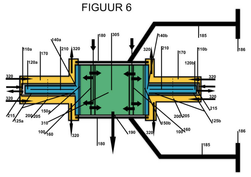
LIJST VAN REFERENTIENUMMERS FIGUUR 5
Behuizing en Structuur:
- 100: Hydraulic Monolith (het monolithische hoofdblok)
- 110 (a/b): Primaire reactie kamers (Twin-configuratie)
- 170: Siloxaan-koelmantel (Isothermal Energy Harvesting)
- 180: Tierods
- 185: Bevestigingsvoeten
- 186: Hydro-pneumatische Puffers
Plunjergroep en Afdichting:
- 120 (a/b): Differentiële plunjergroep
- 125: Labyrint-gasafdichtingen
- 140 (a/b): Stikstofkamer / Nitrogen Ring Layer (NRL) gasveer
- 200: Monolithisch geïntegreerde stikstof-injectiering
- 205: Micro-nozzles voor actieve gasbarrière en centrering
- 210: Interne koelribben (Open-Core Plunjer Cooling)
- 215: Keramische thermische barrière (coating op plunjerkop en reactiekamer wand)
Hydrauliek en Energieoverdracht:
- 150 (a/b): Hermetische balgstructuren (afscheiding olie/stikstof)
- 160: Passieve kleppenstructuur
- 190: Actieve regelklep (\Delta P-5 Stabilization Logic)
- 310: Centraal hydraulisch plenum (vloeistofkern)
- 320: Flow van/naar ITS
Systeemconfiguratie:
- Figuur 5: Axiaal gespiegelde Twin-architectuur (gehele samenstel)
- 305: Centrale symmetrie-as (krachtenbalans)
- SHPA: Schaalbare Array van hydro-puls eenheden
- HVBI: Centraal hydraulisch buffervat